 Process
Analysis Toolkit (PAT) 3.5
Help Process
Analysis Toolkit (PAT) 3.5
Help |
This section shows how to creat a sensor network
model for simulation and verification in PAT. There are a few steps: (A) Creat a new
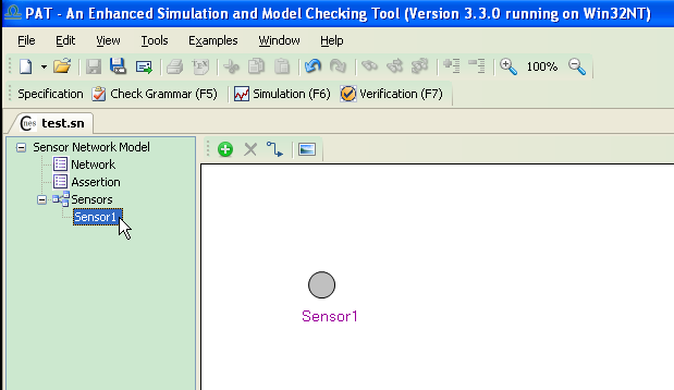
sensor network model From the main menu, click "File -> New -> NESC Model". PAT will creat a sensor network model
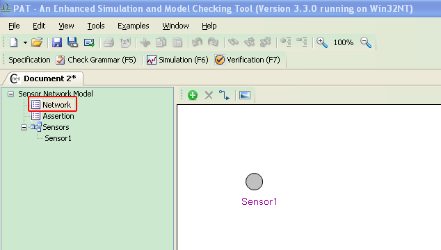
automatically, which has one sensor and the sensor is named Sensor1. (B)
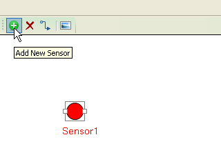
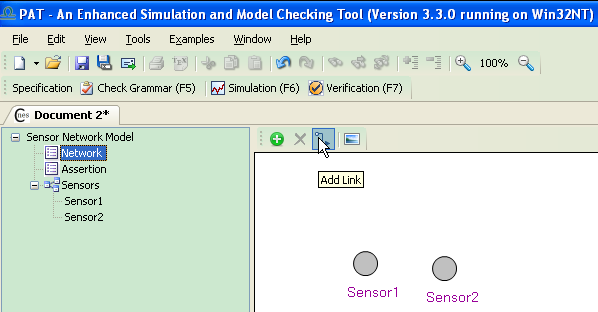
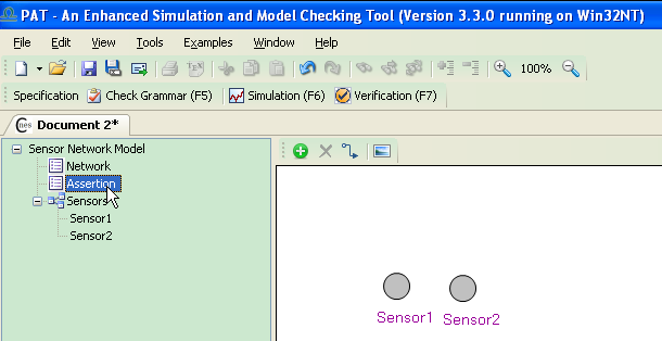
Add sensor nodes and links between them A new sensor will be created by
first clicking the green button on the Network
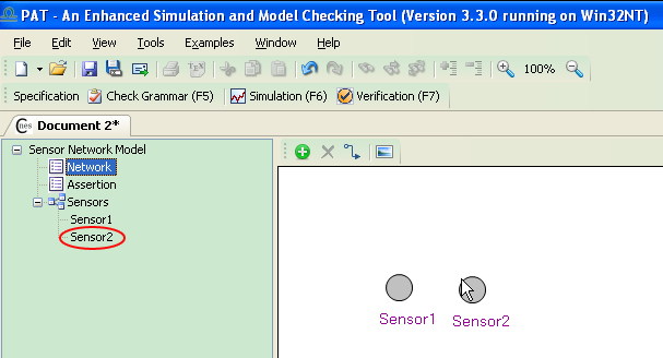
editing panel and then click the white panel to place the new sensor. When a new sensor is created, it is automatically added to the
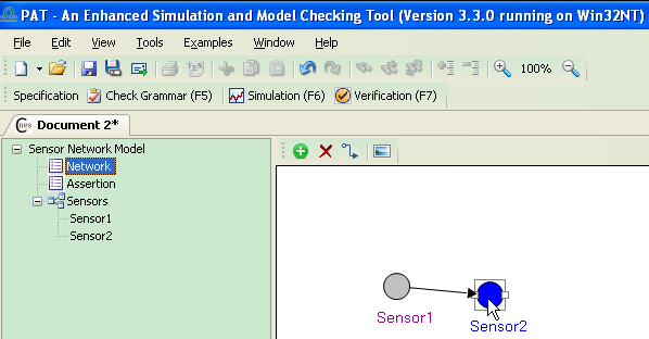
list on the Sensors list on the left of the network editing panel. Similar, clicking the arrow button and then clicking two sensors
sequentially will create a logical link between two sensors. In PAT, a
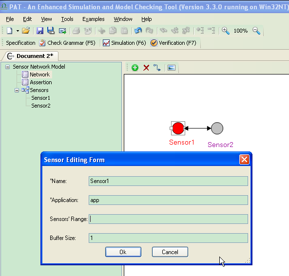
network topology is considered as a directed graph. E.G., adding a data link between sensor1 and sensor2. (C) Edit sensor
information One can view the details of the sensor by double
click it. As shown in the following figure, when a new sensor is created,
it is assigned with "app" application by default. Note that this app
program does not really exist, so the next step is to edit the sensor
information. The table bellow explains each entry in the sensor
editing form:
(A). Creat a new sensor
network model;
(B). Add sensor nodes and
links between them;
(C). Edit sensor
information: assign application for running on them;
(D). Edit verification
goals;
(E).
Simulation;
(F).
Verification.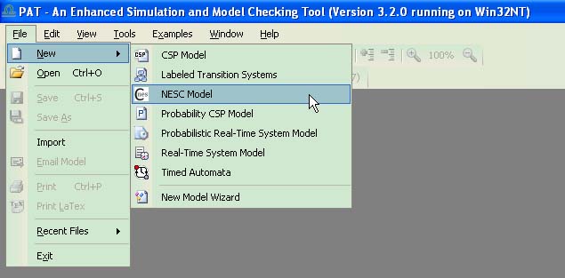
Entry
Meaning
Nullable
Remark
Name
Name of the sensor
No
Each sensor should have a unique name, for accessing its local
status.
TOS_NODE_ID
The unique ID of the sensor
No
Each sensor should have a unique ID, similar what is required in
TinyOS.
Application
The NesC program running on the sensor
No
The model (.sn file) should be
saved in the same path where
there are the source .nc files of the
appointed NesC program.
Sensor's Range
The data range of each sensor device
Yes
If null, PAT will use the default data range ([0,
1]) for sensor devices.
Buffer Size
The size of the buffer for storing incoming msg's
Yes
If null, PAT will use the default size (1) for each sensor.
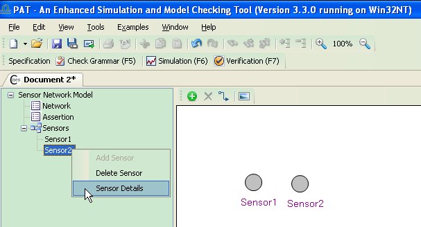
Another way to edit a sensor is to right click it from the Sensors list, which will also open the sensor editing form.
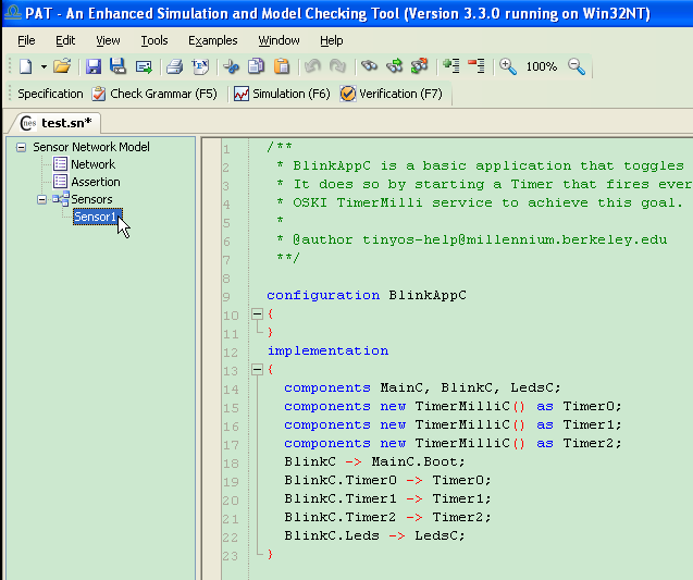
The top-level configuration of the NesC program assigned to a certain sensor can be viewed in PAT editor, by double clicking the sensor from the Sensors list on the left panel.
E.G., the following shows the code of Sensor1. Sensor1 is configured to run a NesC program with BlinkAppC being the top-level configuration/component.
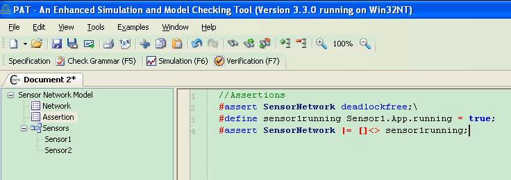
(D) Edit verification goals
Double click Assertion item to switch to the assertion editor.
In the assertion editor, one can edit any number of assertions for verification. The syntax for writing assertions can be found in 3.7.1.5 Assertions.
(E) Simulation
Clicking the Simulation button or pressing F6 will open the Simulation form.
(F) Verification
Clicking the Verification button or pressing F7 will open the Verification form.
Copyright © 2007-2012 Semantic Engineering Pte. Ltd.